



Wheel weight placement is the exact rim location where a balancing machine instructs a technician to add correction mass after measuring the mounted tire-and-wheel assembly. Clip-on weights normally use an approved rim flange; adhesive weights normally use a clean inner-barrel surface. An old weight's location, a vehicle model, or the wheel's appearance alone cannot identify the correct new placement.
The placement decision has three parts: the machine measures the imbalance and angular position, the selected balancing mode identifies one or two correction planes, and the wheel design determines which mounting surface can safely receive the required weight. The wheel-weight format and placement framework helps turn those three inputs into a usable service and stock decision.
The balancer mode that selects the usable planes must also match the wheel design, because a valid correction location depends on both the program and the available rim surface.
Table of Contents
- What does wheel weight placement mean?
- How does a balancing machine determine placement?
- Where do clip-on weights go on a rim?
- Where do adhesive weights go on a rim?
- How do static and dynamic balancing change placement?
- Why is an old weight location not enough?
- What should technicians verify after placement?
- How should buyers plan a placement-ready range?
- Conclusion: Let the measurement lead the placement
- Frequently Asked Questions
- References
What does wheel weight placement mean?
Wheel weight placement means the selected angular position and rim plane for a correction weight. It is not simply “inside” or “outside” the wheel; a correct placement must match the balancer's result, the selected program, and a surface on the wheel that is approved and physically suitable.
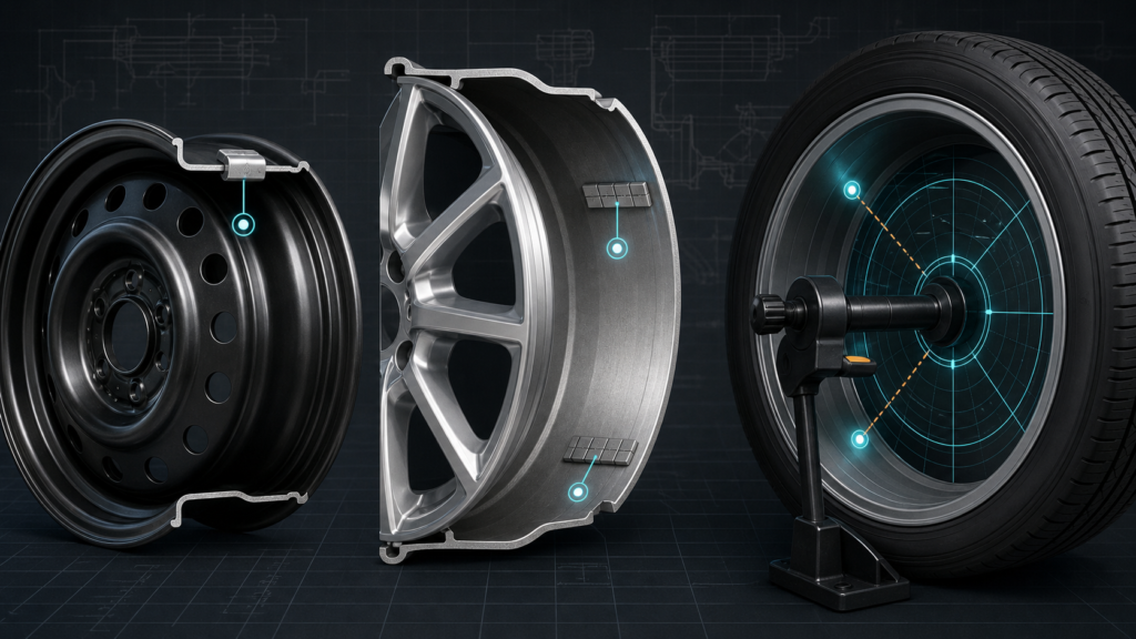
The machine first finds uneven mass distribution in the assembly. It then reports a correction amount and location. On a conventional wheel, the technician may receive a flange location for a clip-on weight. On an alloy wheel, the same balancing requirement may be translated by an alloy-style program into hidden adhesive locations on the barrel.
The correction position matters as much as the correction mass. A correctly weighed part installed at the wrong angle or plane can leave vibration. Continental notes that a dynamic balancing procedure specifies both the amount of weight and where it should be applied 1.
| Wheel and placement situation | Typical approved mounting surface | What the technician must verify |
|---|---|---|
| Steel wheel with a clip-on correction | A compatible rim flange at the plane requested by the balancer | Clip profile, full seating, coating contact, and clearance |
| Alloy wheel with hidden correction | A clean inner-barrel location defined by the selected program | Surface preparation, barrel clearance, segment height, and firm bonding |
| Dynamic two-plane result | Separate inner and outer or approved hidden planes | Each weight's angle and plane, then a verification spin |
| Existing old weight on the rim | No assumed new location | Remove it, inspect the surface, and measure the current assembly |
How does a balancing machine determine placement?
A balancing machine determines placement by spinning a correctly mounted tire-and-wheel assembly, measuring imbalance, and calculating the angular position and correction plane or planes. The operator must enter the wheel dimensions and select a program that represents the usable rim locations.
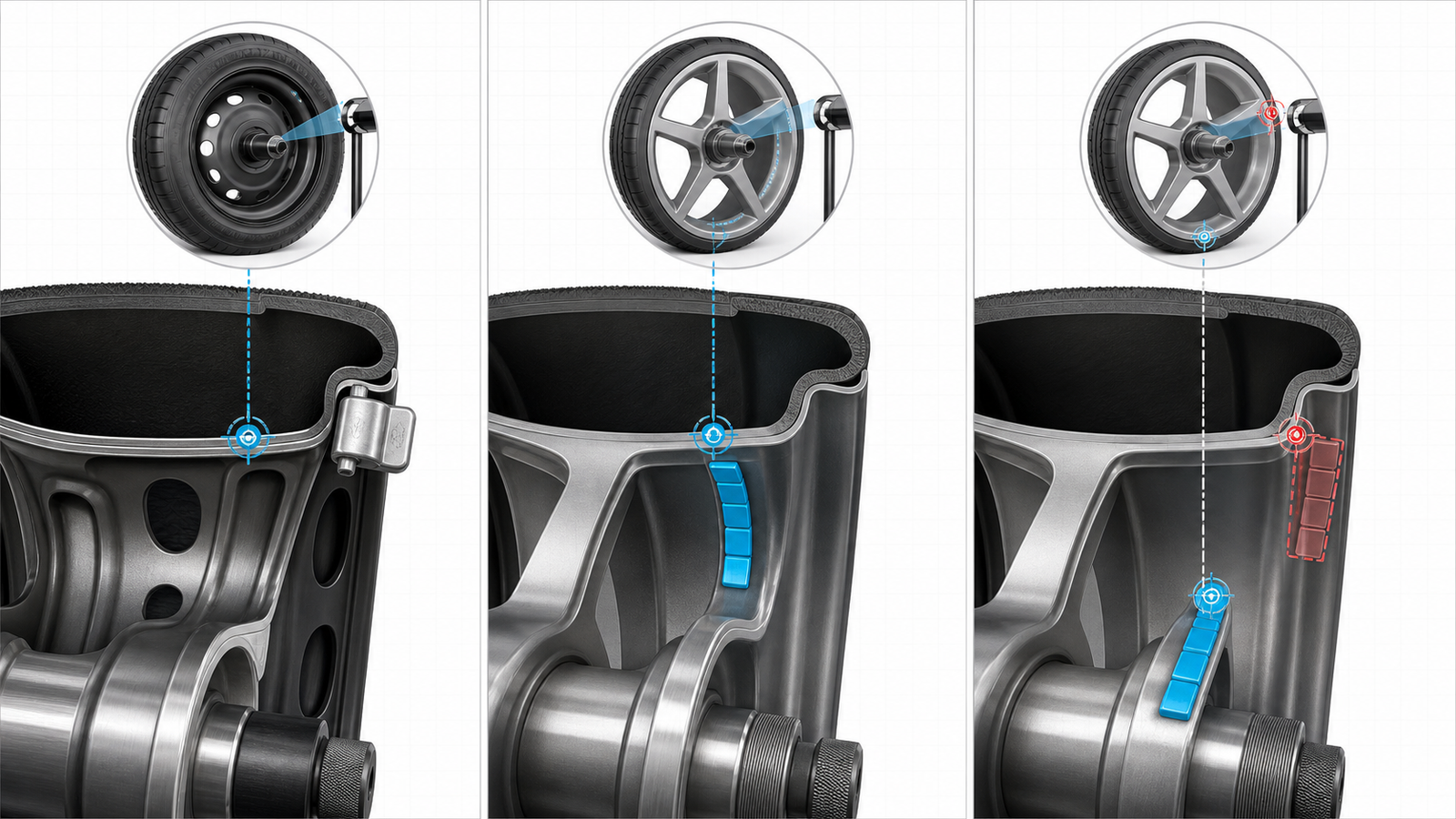
The machine identifies a correction angle; the program and the wheel surface determine whether a clip-on or adhesive format can be installed at that point.
The machine does not merely find a “heavy side.” Modern two-plane balancing also distinguishes the inner and outer correction planes. The wheel dimensions entered by the technician tell the machine where those planes are located relative to the spindle. Inaccurate dimensions, a poorly centered wheel, or the wrong program can therefore create a placement instruction that does not match the actual wheel.
This is why placement starts before the weight is selected. Inspect the wheel, identify usable clip-on or adhesive surfaces, mount it correctly, select the appropriate mode, and then follow the indicated location. If a requested position is unavailable, do not improvise a nearby spot; use an approved alternative program or wheel-specific procedure and recheck the assembly.
Where do clip-on weights go on a rim?
Clip-on weights go on a rim flange that is designed or approved to accept the matching clip profile at the correction location requested by the balancer. The weight must engage the flange fully, sit at the intended angle, and clear nearby wheel features.
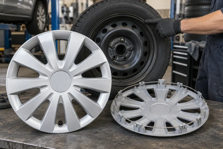
Steel wheels often have accessible flange locations and are common clip-on applications. That does not make every steel flange interchangeable. The clip needs to match the lip thickness, gap, contour, coating, and local clearance. Buyers serving these applications can use steel-wheel flange placement checks to connect a clip-on decision with the real rim profile rather than a general wheel category.
Some alloy wheels also have approved clip-on locations, usually with particular attention to finish protection and clip construction. Many appearance-sensitive alloy wheels do not. Forcing an unmatched clip can chip a finish, deform the clip, prevent full seating, or cause a later retention issue.
Before installing a clip-on weight, confirm that the indicated location is on the approved flange, the clip profile is correct, and the weight will not touch a wheel cover, brake component, or decorative feature. Use the correct tool; a hard strike cannot convert a wrong clip profile into a secure fit.
Where do adhesive weights go on a rim?
Adhesive weights go on a clean, dry, approved section of the inner wheel barrel, usually in a location that hides the weight and supports the plane requested by the balancing program. The tape needs full contact on a suitable surface, with enough clearance for the weight's height, length, and curvature.
Alloy wheels commonly use adhesive weights because the inner barrel preserves the appearance of the visible flange and allows hidden placement. A two-plane alloy-style program may call for two distinct inner-barrel positions rather than a visible outer flange weight. Michelin's explanation of static and dynamic balancing illustrates that placement is tied to the balancing method rather than a generic “one place on every rim” rule 2.
Surface preparation is part of placement. Brake dust, moisture, tire lubricant, old tape residue, or a curved surface that prevents contact can make an otherwise correct location fail in service. Before applying the strip, remove residue, clean the surface as appropriate, allow it to dry, and press the weight firmly at the indicated angle.
Once the plane is known, the attachment choice after the plane is known becomes straightforward: use a clip-on product only where a compatible flange exists, and use adhesive only where the barrel surface and placement guidance support it.
How do static and dynamic balancing change placement?
Static balancing uses one correction plane, while dynamic balancing uses two planes to address side-to-side couple effects as well as circumferential imbalance. The difference determines whether the balancer asks for one location or separate inner and outer locations.
In a static procedure, the correction is made in the program's single designated plane. That plane may be a central rim location or another approved location determined by the machine and wheel program. In a dynamic procedure, the machine can request corrections at two different planes, often associated with the inner and outer sides of the rim.
The most visible practical change is on styled alloy wheels. Instead of placing a weight on the outer flange, an approved program may route both dynamic corrections to hidden locations inside the barrel. The instruction is not “move the weight wherever it is invisible”; it is to use the specific hidden planes the balancer calculates for that program.
For any method, follow the readout and then run a verification spin. Hunter's balancer documentation emphasizes placement guidance and balance conditions as part of the machine workflow 3. A post-installation check is the only reliable way to confirm that the selected location and format delivered the intended correction.
Why is an old weight location not enough?
An old weight location is evidence that previous work happened; it is not a specification for the current tire-and-wheel assembly. New tires, tire rotation, wheel damage, wear, a changed mounting orientation, or a previous incorrect repair can all change the measured imbalance and required placement.
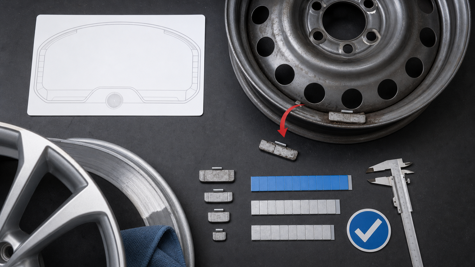
Remove old weights and remeasure the current assembly. The new correction angle, plane, and format must come from the current balancing result.
Do not copy the old angle, stack a new weight beside it, or assume the old product type is still correct. Remove the old weight carefully, inspect the rim for residue or damage, and balance the complete current assembly. If a strip was present, clean the barrel before any new adhesive installation. If a clip-on weight was present, verify the flange and clip family again rather than reusing a bent or unknown part.
What should technicians verify after placement?
After placement, technicians should verify that the weight is fully seated or fully bonded, clears nearby components, appears in the machine-indicated location, and produces an acceptable recheck result. Visual inspection alone cannot prove the wheel is balanced.
For clip-on weights, check engagement, orientation, finish contact, and clearance. For adhesive strips, check clean contact across the tape, correct segment count, pressure, and clearance along the barrel. Then complete a verification spin using the same wheel data and program. If the result is not acceptable, investigate wheel centering, entered dimensions, surface condition, and actual placement before adding more weight.
The goal is not to use the minimum number of parts at any cost; it is to make the correct correction at the correct location with a format that remains secure. This reduces comebacks, lost weights, cosmetic complaints, and unnecessary repeat balancing.
How should buyers plan a placement-ready range?
Buyers should plan a range that lets technicians complete the placements their common wheels and balancer programs require. That normally means validated clip-on profiles for recurring steel-wheel flanges, adhesive strips for alloy-wheel barrel locations, and increments that align with the local balancing workflow.
Begin with the workshop's real wheel mix. Record recurring steel flanges, alloy-barrel surfaces, preferred balancing modes, and the gram or ounce increments requested most often. Then test clip profiles on representative flanges and adhesive strips on representative cleaned barrels. Do not select the range from generic product photos alone.
For mixed service channels, evaluate clip-on and adhesive formats for actual rim surfaces by the approved surfaces and correction planes they must cover. Clear labels, separate trays, and sample records help technicians select the correct format when the balancer identifies a placement.
Conclusion: Let the measurement lead the placement
Wheel weights go where the balancing machine, selected program, and approved wheel surface say they should go. A clip-on weight belongs on a compatible rim flange; an adhesive weight belongs on a prepared inner-barrel surface. Neither format should be moved just because another position is easier to see or reach.
Balance the current assembly, follow the indicated angle and plane, verify fit or adhesion, and complete a recheck spin. Buyers can then build a static and dynamic correction across one or two planes around real wheel surfaces, not assumptions from prior repairs.
Frequently Asked Questions
Where should wheel weights be placed on a rim?
They should be placed at the angular position and correction plane identified by the balancing machine, using an approved surface on that wheel. Clip-on weights use a compatible rim flange; adhesive weights use a clean inner-barrel location.
Can I put a wheel weight anywhere on the rim?
No. Moving a weight changes its balancing effect and can create clearance, finish, or retention problems. Use the location provided by the selected balancer program and verify the result after installation.
Why are wheel weights sometimes inside the rim?
Adhesive weights are often placed inside the barrel to protect the visible flange and to meet hidden-placement instructions on alloy-wheel balancing programs. Dynamic balancing may use two separate inner-barrel locations.
Do clip-on wheel weights always go on the outer flange?
No. They go on an approved flange at the plane requested by the machine. The exact side and location depend on the wheel design, balancing mode, and compatible clip profile.
Should I reuse an old wheel weight position?
No. Remove the old weight and rebalance the current tire-and-wheel assembly. The previous position does not prove the new correction angle, plane, or weight type.
What causes wheel weights to be placed in the wrong spot?
Common causes include incorrect wheel dimensions entered into the balancer, poor centering on the spindle, the wrong balancing mode, moving a weight for appearance, a mismatched clip, or an adhesive strip that cannot be installed at the indicated location.
References
[1] Continental. “Balancing Tires.” 2026.
[2] Michelin. “Motorcycle Wheel Balancing.” 2026.
[3] Hunter Engineering Company. “Road Force Elite Wheel Balancer Operations Manual.” 2020.