



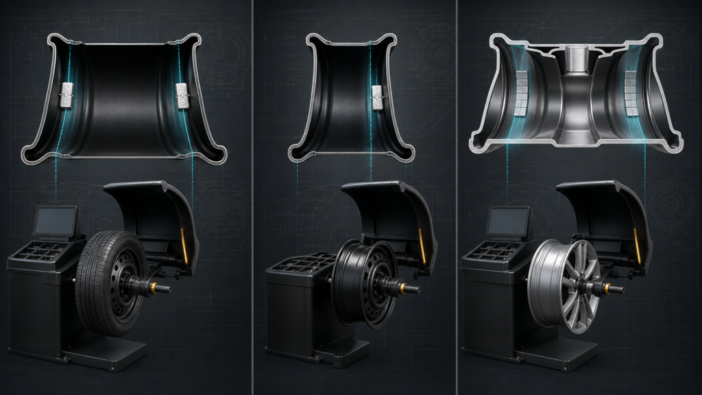
Wheel balancer modes tell the machine which correction planes and weight locations are available on a particular wheel. Standard mode commonly represents a conventional two-plane setup, Static mode uses one correction plane, and ALU-style programs adapt two-plane balancing to alloy-wheel locations such as adhesive or hidden inner-barrel positions. The exact labels and diagrams vary by balancer brand, so the machine's manual and wheel guidance remain the final authority.
The mode is not a marketing setting. It changes the geometric model the balancer uses when it turns a measured imbalance into weight positions. Select the wrong mode and the machine may ask for a valid correction mass at a surface that the actual wheel cannot use. The wheel balancing format and range context helps service teams connect these program choices to rim type, attachment method, and stock planning.
For a machine output to become an installation instruction, teams must also follow machine-led placement on the rim rather than selecting a convenient location by appearance alone.
Table of Contents
- What do wheel balancer modes do?
- What is Standard or dynamic mode?
- What is Static mode?
- What does ALU mode mean?
- How does a balancer mode change weight placement?
- Why do ALU mode names vary by machine?
- How should technicians select a mode?
- What should shops and buyers plan for?
- Conclusion: Select the wheel model before the weight
- Frequently Asked Questions
- References
What do wheel balancer modes do?
Wheel balancer modes define the correction planes that the machine will use for its calculation and display. They connect the measured tire-and-wheel assembly to the wheel's practical mounting surfaces, such as two rim flanges, a single plane, or two hidden positions inside an alloy-wheel barrel.
The machine still measures the same rotating assembly, but it needs a realistic map of where a technician can place a weight. A conventional steel wheel may offer two accessible flange planes. A styled alloy wheel may have no suitable visible outer flange and instead need two adhesive locations inside the barrel. The selected mode tells the balancer how to translate the measurement into those surfaces.
This also explains why balancing should not begin with a preferred box of weights. The balancing process and wheel-weight relationship comes first: the machine measures imbalance and the chosen wheel model determines where correction can be installed.
What is Standard or dynamic mode?
Standard mode—often called Dynamic, DYN, or a similar label—normally models two conventional correction planes on the inner and outer sides of a rim. It is commonly used when the wheel has accessible locations for the indicated weights, such as a steel rim that accepts matching clip-on profiles.
The key idea is two-plane correction. The balancer calculates a mass and angle for each plane when the assembly needs them. Depending on the result, one plane may require no weight, but the program remains capable of correcting both side-to-side and radial effects. Continental describes dynamic balancing as a computer-guided process that can specify weights on both inner and outer rim locations 2.
Standard mode does not mean every steel wheel uses the same clip or that every visible rim edge is a valid mounting point. The actual clip must still match the rim flange, and the wheel must be centered correctly on the balancer. It simply means the program is using a conventional two-plane geometry.
What is Static mode?
Static mode uses one correction plane to address a single-plane imbalance. It is useful where the wheel, service procedure, or available mounting surface calls for a one-plane correction rather than separate inner and outer weights.
In static mode, the machine reports a single correction amount and location according to its defined plane. That does not require a visible center weight on every wheel: the actual location depends on the balancer's procedure and the available rim surface. The important distinction is one plane, not two.
Static mode can be appropriate for narrow wheels or specific applications, but it is not a shortcut for a two-plane wheel that needs dynamic correction. A wheel that is wide enough to produce meaningful side-to-side effects may need dynamic balancing even if a single weight looks simpler. Follow the machine manual and the wheel's service guidance rather than choosing static only to reduce the number of weights.
What does ALU mode mean?
ALU mode is a family of alloy-wheel balancing programs that keeps the two-plane balancing concept but places the correction weights on different, often hidden, rim surfaces. Most ALU variants are designed around adhesive weights, mixed clip-and-adhesive placement, or specific inner-barrel planes that protect the visible wheel face.
For example, one ALU-style program may request adhesive weights at two inner-barrel locations; another may combine an inner clip-on position with an outer adhesive position; a variable-plane version may let the operator measure the actual hidden adhesive locations. These are not universal code definitions. A current wheel-balancer manual can offer several ALU programs with different combinations of adhesive and clip-on locations 3.
The stable rule is simple: ALU mode is about the geometry of the correction planes and the available mounting surfaces, not merely about a wheel being made from aluminum. A steel wheel can sometimes require a nonstandard placement; an alloy wheel can sometimes have an approved clip-on location. Verify the actual wheel rather than selecting a mode from material alone.
How does a balancer mode change weight placement?
The selected mode changes the plane geometry that the balancer uses, so it changes where the display directs the technician to place correction weights. Accurate rim dimensions are essential because the machine calculates the correction position from that geometry.
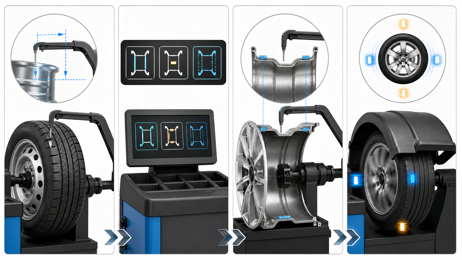
Measure the wheel, select a mode that represents its usable surfaces, define hidden planes when required, then verify the completed balance.
| Mode family | Correction-plane model | Typical mounting approach | Key operator check |
|---|---|---|---|
| Standard / Dynamic | Two conventional inner and outer planes | Clip-on weights on compatible flange locations | Confirm flange fit, wheel data, and visibility requirements |
| Static | One defined plane | One approved rim location or single-plane procedure | Confirm that a one-plane procedure is appropriate for the wheel and service task |
| ALU-style preset | Two planes adapted to rated alloy-wheel geometry | Adhesive/adhesive or a mixed clip-and-adhesive arrangement | Match the displayed diagram to the actual wheel's usable surfaces |
| ALU variable-plane | Two technician-measured adhesive planes | Hidden inner-barrel locations selected on the actual wheel | Measure both positions accurately and maintain tape clearance |
Moving a weight to a convenient position after the mode is selected can undo the calculation. If the program offers a hidden or split-weight function, use that function and recheck the result. Hunter's wheel-balancer documentation likewise treats placement guidance and final balance conditions as part of the balancing workflow 1.
Why do ALU mode names vary by machine?
ALU labels are product-interface names, not a single industry-wide map. One machine's ALU1 can mean two adhesive locations, while another model may reserve its first ALU option for a mixed arrangement or call a variable-plane function ALU-S, ALU-P, or another name.
This difference matters for training. A technician who knows that “ALU2” meant adhesive-inside plus clip-outside on one machine should not assume the same display on another machine requests the same combination. Inspect the screen's rim diagram, read the relevant manual section, and compare the indicated planes with the actual wheel before spinning.
When documenting a service procedure, record the equipment model, selected mode, wheel dimensions, and the observed weight positions. That is much more useful than a note that only says “used ALU.” It helps the next technician reproduce the correct geometry rather than rely on a familiar label.
How should technicians select a mode?
Technicians should select a mode from the wheel's approved weight surfaces and required correction planes, then enter or measure the wheel dimensions accurately. The choice should be made before the spin, not after the balancer has issued a conventional placement that will not work on the rim.
Use this selection sequence:
- Inspect the wheel for accessible flanges, cosmetic surfaces, inner-barrel space, brake clearance, and existing damage or residue.
- Identify which surfaces are approved for clip-on or adhesive weights.
- Select Standard/Dynamic for conventional two-plane locations, Static for a validated one-plane procedure, or the ALU variant whose displayed rim diagram matches the actual surfaces.
- Measure the rim dimensions or use the machine's measuring arm as required by the mode.
- Install weights at the indicated angles and planes, then run a verification spin.
After the mode identifies the plane, use weight attachment after mode selection to choose the product format. A clip-on weight needs a matched flange profile; an adhesive weight needs a clean, dry, suitably shaped barrel surface. Neither product can make an incorrect mode selection correct.
What should shops and buyers plan for?
Shops and buyers should plan for the modes their common wheels actually require. A range built only around clip-on weights may leave an alloy-wheel shop unable to complete hidden ALU placements, while an adhesive-only range may leave routine steel-wheel flange service inefficient.
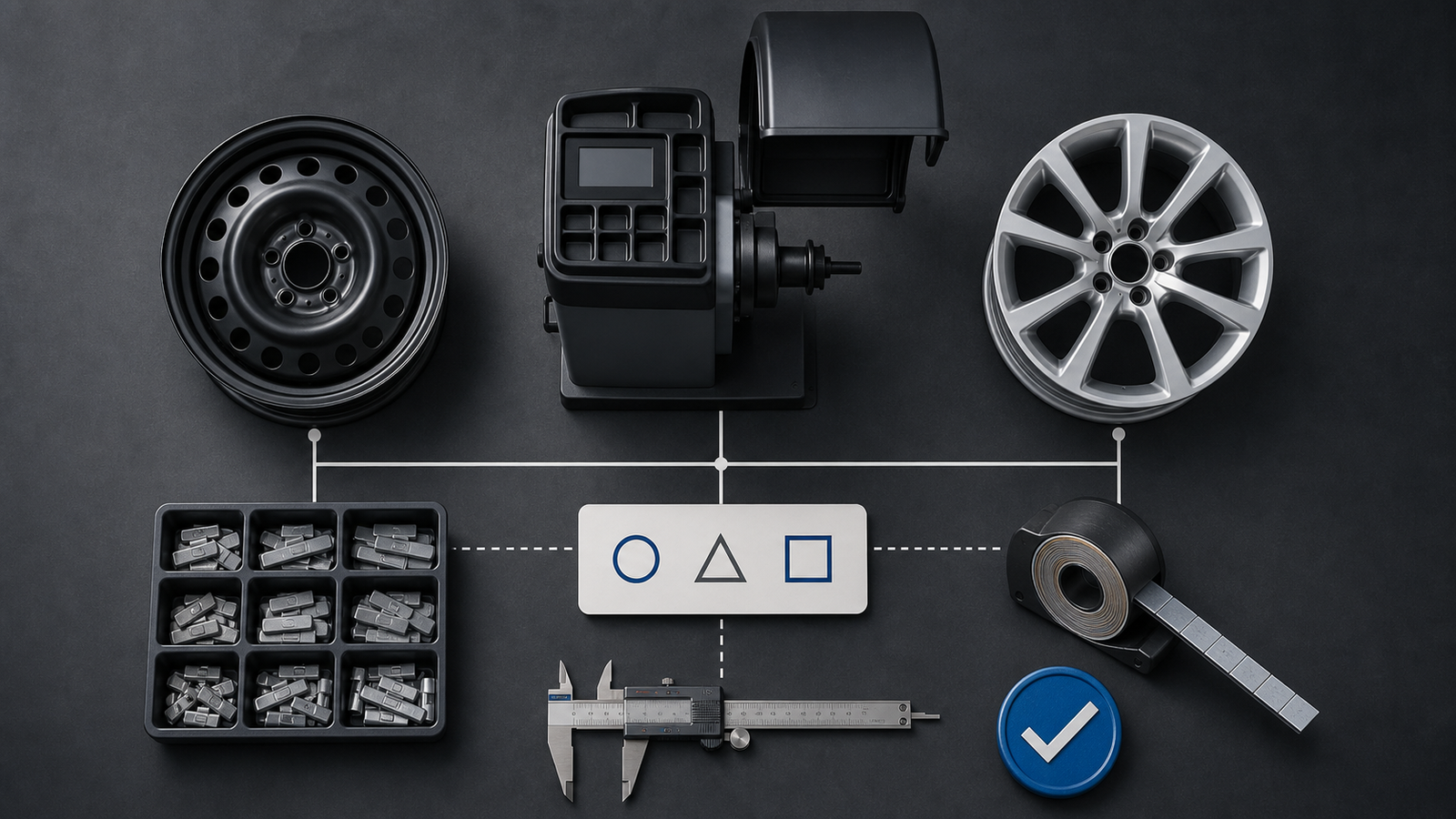
The balancer, wheel mix, and approved correction surfaces together determine the clip-on and adhesive formats a service range needs.
Start with a sample of normal service work: common steel wheels, alloy wheels, tire sizes, balancer models, and frequently selected modes. Then validate the relevant clip profiles on representative flanges and the adhesive strip dimensions on representative barrel surfaces. The result should be a practical matrix of mode, wheel family, correction format, and size system.
Buyers serving both wheel types can evaluate weight formats for standard and alloy-wheel service around the actual correction planes their customers use. Clear labels and separate trays reduce the chance that a technician selects a clip-on weight when the mode requires a hidden adhesive plane, or the reverse.
Conclusion: Select the wheel model before the weight
Standard, Static, and ALU programs are different wheel models inside the balancer. Standard mode commonly represents two conventional planes; Static mode uses one plane; ALU-style modes adapt two-plane correction to alloy-wheel or hidden mounting surfaces. The labels can vary, but the placement principle does not.
Inspect the wheel, choose the program whose diagram matches usable surfaces, measure the geometry accurately, and verify the final spin. Buyers can then build a static-versus-dynamic balancing method that supports the shop's real balancer modes instead of a generic parts list.
Frequently Asked Questions
What is ALU mode on a wheel balancer?
ALU mode is an alloy-wheel program family that adapts two-plane balancing to adhesive, hidden, or mixed weight locations. The exact ALU1, ALU2, or ALU-S diagrams depend on the balancer manufacturer and model.
Should I use Standard mode for every steel wheel?
Not automatically. Standard/Dynamic mode is common for conventional two-plane steel-wheel balancing, but the clip profiles, flange locations, wheel dimensions, and service procedure still need to be correct.
Does Static mode mean one weight in the center of every wheel?
No. Static mode means one correction plane. The exact approved location depends on the balancer's procedure and wheel geometry, and a one-plane procedure should not replace dynamic balancing where two-plane correction is required.
Can ALU modes use clip-on weights?
Some machines have ALU variants that combine clip-on and adhesive weights; others may use two adhesive locations. Read the rim diagram and manual for the specific machine rather than assuming an ALU label always means adhesive only.
Why does a balancer ask for weights in a hidden location?
The selected alloy-style mode may map the correction planes to inner-barrel surfaces to protect the visible wheel face. The technician must use the exact positions the mode identifies and verify the final balance.
What happens if I select the wrong balancer mode?
The machine can calculate correction positions for the wrong rim geometry. Even if the displayed mass is plausible, the weight may be placed on an unsuitable surface or at the wrong plane, leaving residual imbalance or causing fitment problems.
References
[1] Hunter Engineering Company. “Road Force Elite Wheel Balancer Operations Manual.” 2020.
[2] Continental. “Balancing Tires.” 2026.
[3] Aston Technologies. “AWB-139MLT Wheel Balancer User Manual.” 2026.