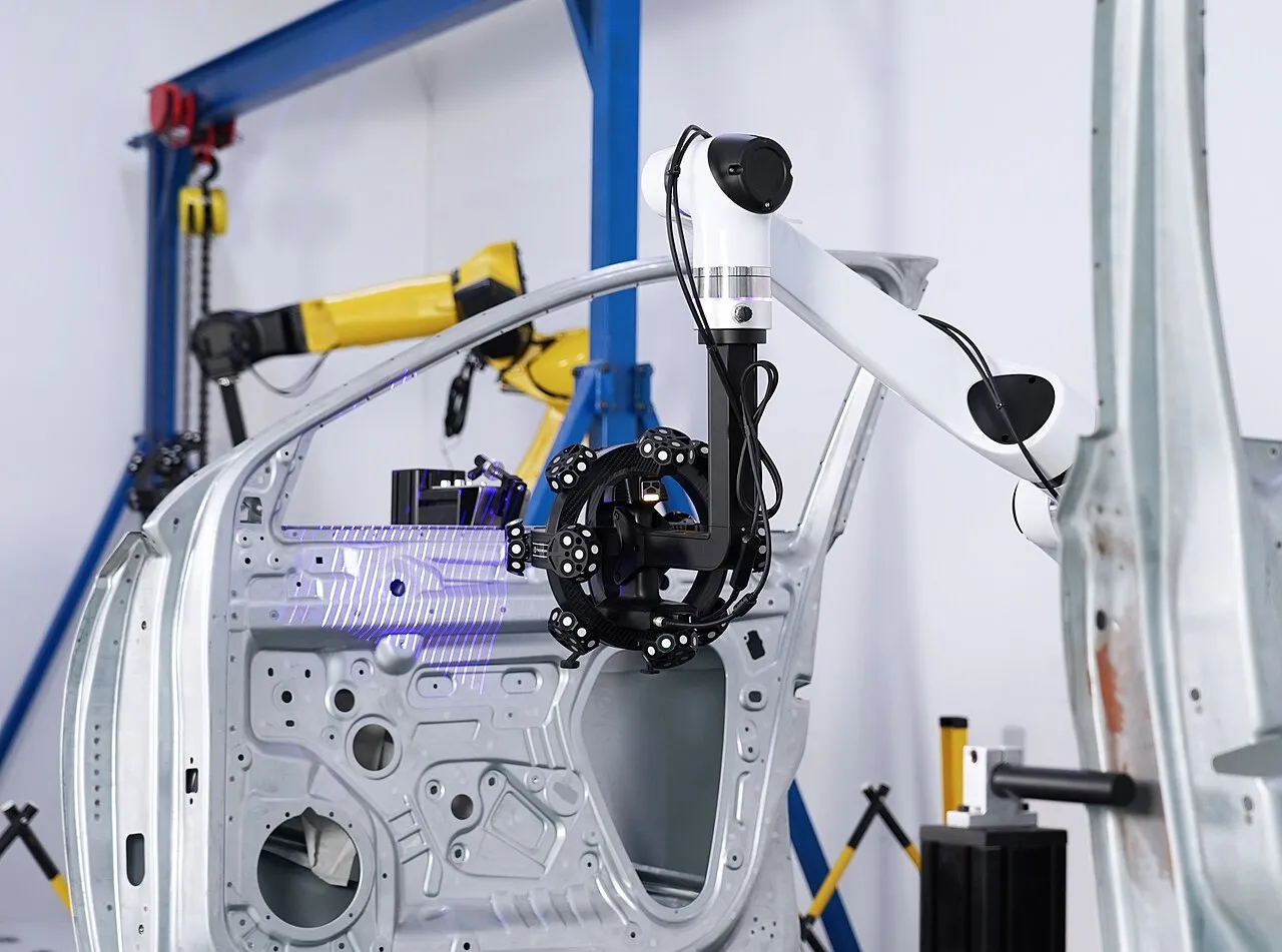
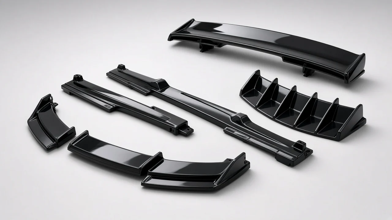
3D scanning and reverse engineering for car parts and vehicles: scan an OE part, a sample or a vehicle body, turn the scan into CAD, and use it to tool and inspect new exterior parts. Yirox scans with a Shining3D EinScan HX handheld scanner (0.04 mm accuracy) and supplies mesh, reverse-engineered STEP/IGES, deviation color maps and inspection reports.
| Item | Yirox capability |
|---|---|
| Scanner | Shining3D EinScan HX, handheld, blue laser and infrared |
| Accuracy | 0.04 mm |
| Large-part stitching | 0.1 mm/m |
| Mesh output | STL, PLY |
| CAD output | STEP, IGES (reverse-engineered; not the original OEM CAD) |
| Inspection output | Deviation color map PDF/PNG at ±0.5 or ±1.0 mm scales; inspection report PDF |
| Point cloud | ASC |
| Follow-on processes | DFM, mold making, injection molding, painting, chrome plating, CMM |
| Confidentiality | NDA available |
After the scan, we recommend the material: PP and TPO for bumper and flare parts or two-shot molding material pairs for parts with soft seal edges. To see how scanning fits the way you buy, compare auto parts solutions by buyer type.
Reverse engineering is the process of creating a CAD model from a physical object when the original design data is not available. 3D scanning is the fastest and most accurate way to capture that object. A scanner records millions of points on the surface, which become a mesh.
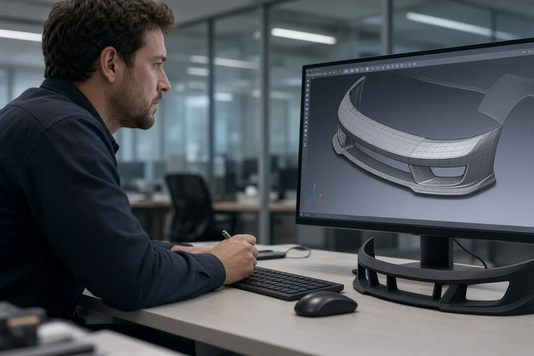
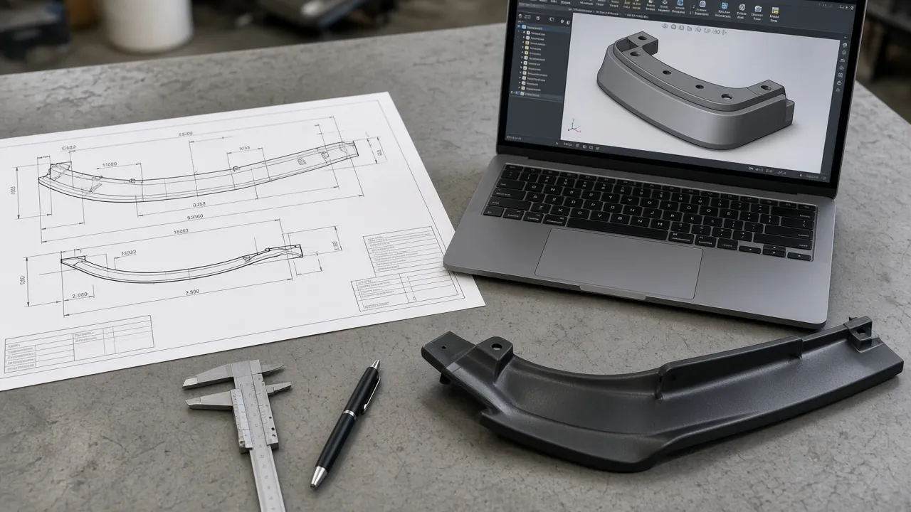
Engineers then rebuild clean CAD surfaces from the mesh so the part can be modified, tooled and manufactured. In a 3D scanning reverse engineering project, the scan is only the first step: the real output is clean CAD that a mold maker can use for reverse engineering car parts that fit.
In the automotive aftermarket this is common. A brand wants to make a spoiler for a new model, but has no OEM CAD for the trunk lid. Or a buyer has an old part with no drawings and wants a better version. Scanning the car or the part gives the shape, and reverse engineering turns it into data a mold shop can use.
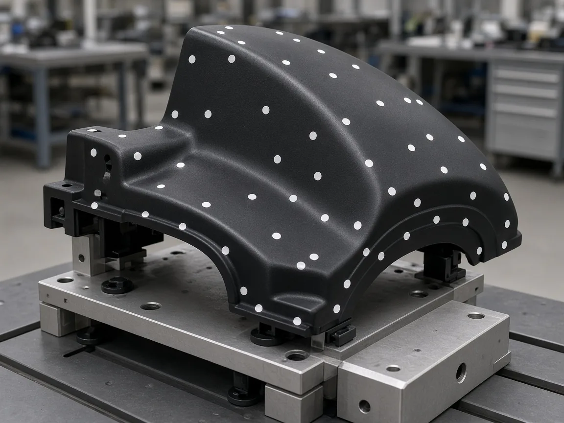
Our scanner projects blue laser lines (or an infrared pattern) onto the surface and reads them with cameras. From the shape of the lines the software calculates the 3D position of each point. As the operator moves the scanner around the part, the software stitches the frames into one model using markers or the part’s own geometry.
Blue laser is good for detailed, shiny or dark surfaces, which are common on painted car parts. Infrared mode is faster for large areas such as a vehicle body. For long parts and vehicles, stitching accuracy matters as much as single-frame accuracy; our scanner holds 0.1 mm per meter.

Buyers often ask for “the scan”, but a raw scan and a usable CAD model are different things.

| Output | What it is | Use it for |
|---|---|---|
| Point cloud (ASC) | Raw measured points | Archive, custom processing |
| Mesh (STL / PLY) | Triangulated surface from the scan | Viewing, 3D printing, comparing, designing around |
| Reverse-engineered CAD (STEP / IGES) | Rebuilt surfaces and features | Product design, mold design, CNC machining |
| Deviation color map (PDF / PNG) | Scan compared to CAD with color scale | Inspection, fit problems, approval |
| Inspection report (PDF) | Measured results and comments | Quality records, supplier approval |
Reverse-engineered CAD is a new model based on measurement. It is not the original OEM design data, and we label it that way in every delivery.

To design a body kit, spoiler or trim that fits a new model, we scan the mounting surface on the vehicle.
Scan an OE or competitor part to capture its shape, then improve it: change the material, add clips or adjust the styling.
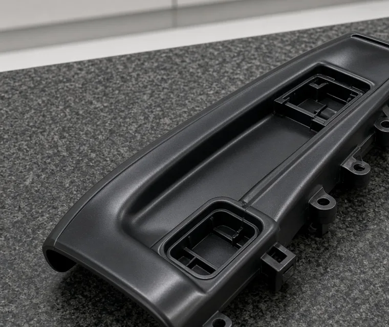
Scan a molded part and compare it with CAD to see warpage or fit problems across the whole surface.
Old parts without drawings can be scanned to keep a digital record for future tooling.
Not sure your part can be scanned?Send photos of the part and we will tell you how we would scan it for reverse engineering and what you receive.
Most exterior parts scan well, but some surfaces need care. These are general points that apply to handheld scanning.
Single-frame accuracy of 0.04 mm is fine enough to capture small features on clips and edges. On a long part, the stitching error of 0.1 mm per meter is the figure to watch: on a 1.5 m spoiler, stitching adds up to about 0.15 mm. Both are well within the ±1.0 mm general and ±0.5 mm critical tolerances we hold on molded exterior parts.
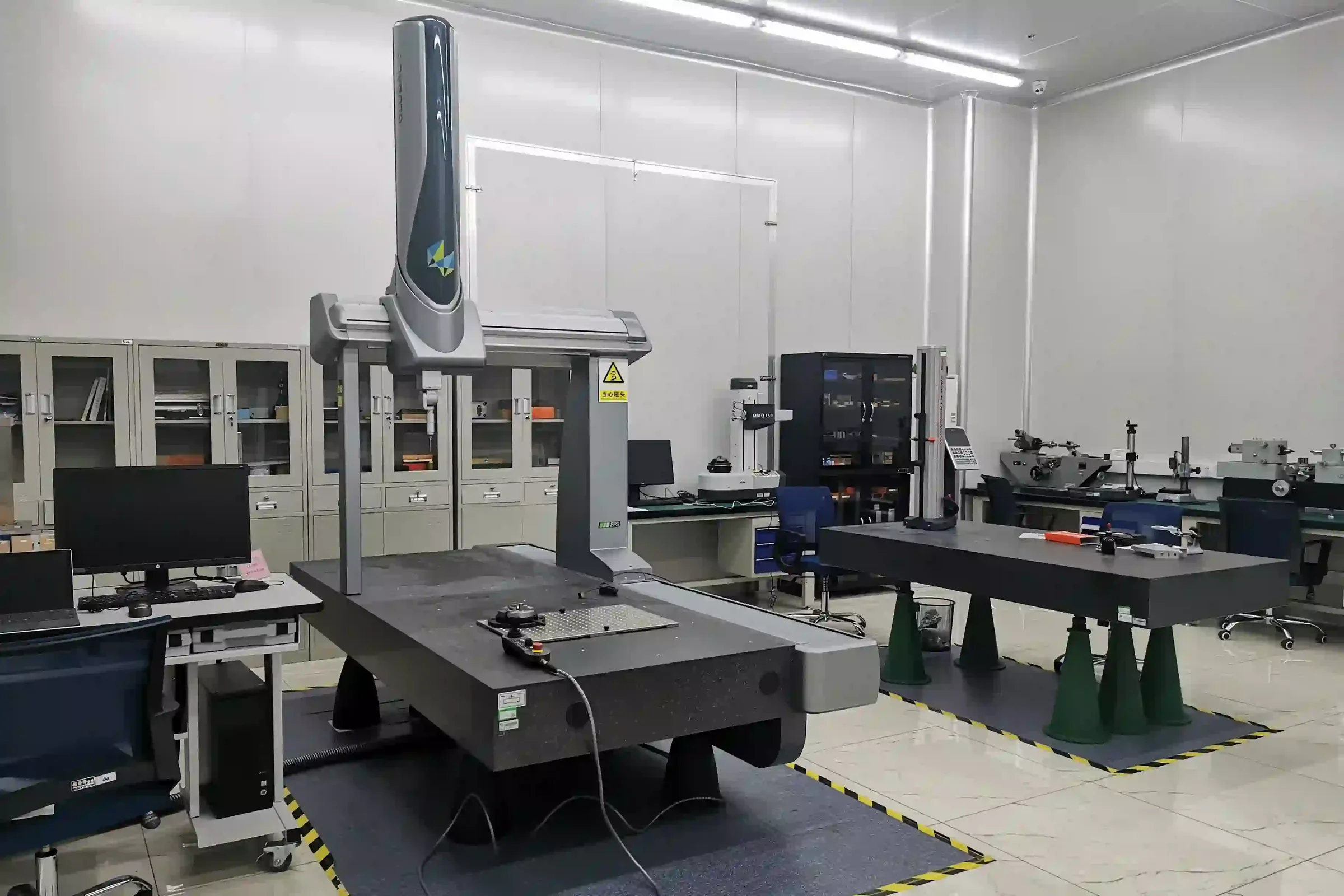
For the tightest inspection, we combine scanning with CMM. The scan shows the full surface, and the CMM measures critical points with higher accuracy. See our CMM inspection page.

Scan the front bumper, sides and rear of the vehicle, then design a lip, side skirts and diffuser that follow the body surface and use existing mounting points.
Scan the trunk lid or tailgate to design a spoiler that sits flush, with tape or clip areas matched to the real surface.
Scan a used OE part, repair damaged areas in CAD and build a new mold for a replacement part.
Scan your current product, change the styling or add clips, and keep the proven fit.
Scan parts from another supplier and compare them with CAD to find out why they do not fit.
| Advantages | Limitations |
|---|---|
| Captures complex curved surfaces quickly | The result is measured data, not the original design intent |
| Works on vehicles, not just loose parts | Shiny or transparent surfaces need preparation |
| Gives a full-surface comparison to CAD | Large parts need careful stitching |
| Speeds up aftermarket product development | CAD rebuild time depends on part complexity |
We check what needs to be scanned, the surfaces that matter and how the new part will mount.
The part is cleaned and marked if needed, then scanned with the handheld scanner. Vehicles are scanned at the mounting area.
Scan data is cleaned, aligned and exported as a mesh (STL or PLY) and point cloud (ASC).
Engineers rebuild surfaces and features as STEP or IGES CAD. This is reverse-engineered data, not the original CAD.
Your new part is designed on the scan data and reviewed for molding, finishing and fit.
Prototypes or first articles are scanned again and compared to CAD with a deviation color map.
A scan is a measurement; a mold needs a design. Between the two, engineers make decisions that affect how the part is molded and finished.

Because our engineers also run DFM for our mold shop, scan data becomes a moldable design without a hand-over between companies. See injection molding for the next steps.
Larger areas take longer to scan and stitch.
Shiny, dark or transparent surfaces need preparation.
A mesh is faster to deliver than full CAD rebuild.
Many features, clips and blends take more engineering time.
Color maps and reports add analysis time.
If the data is used for tooling with us, scanning is part of the program.
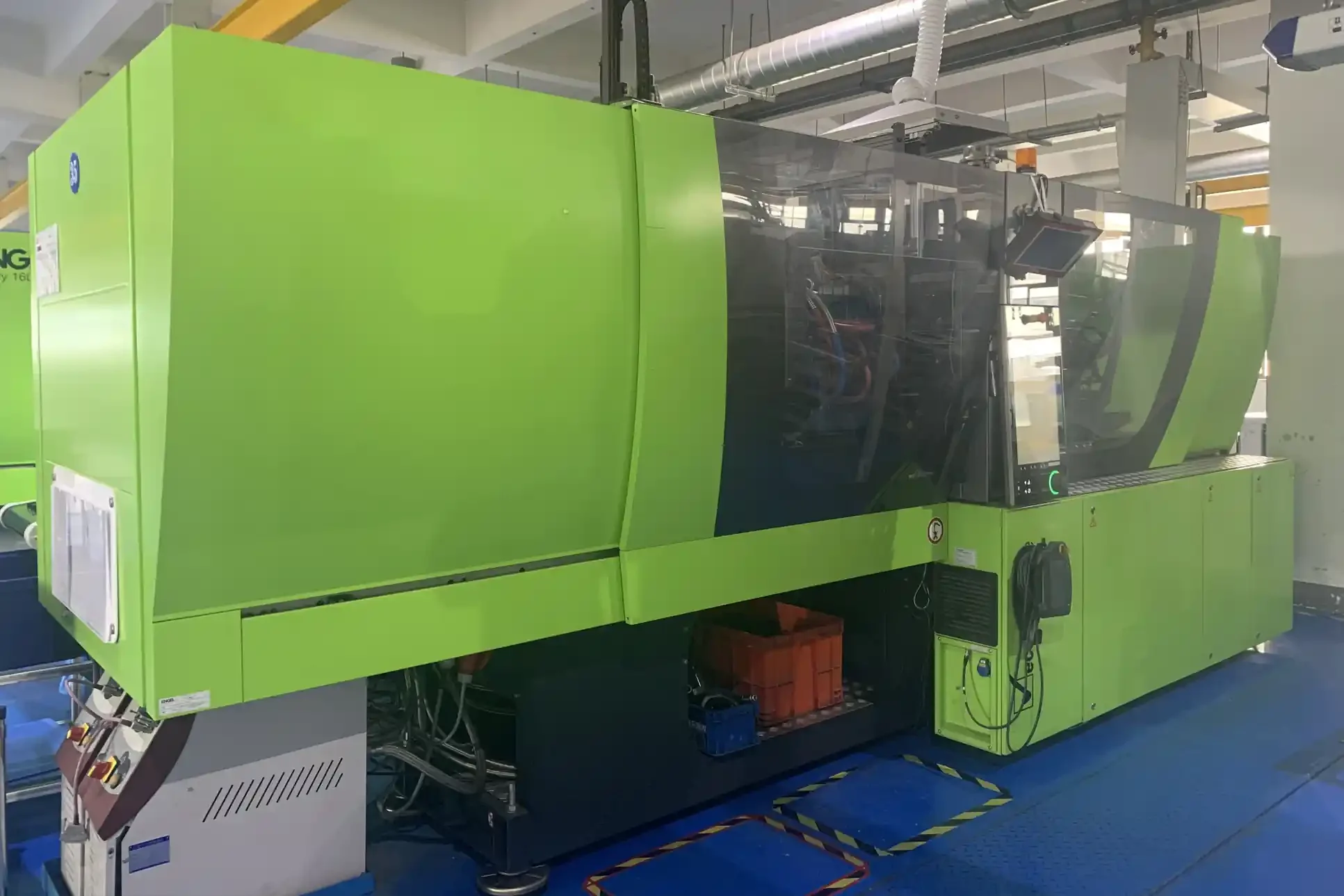
Scanning is most valuable when the same team uses the data to build the mold and make the part. At Yirox the scan goes straight to our engineers, then to our mold shop, injection molding machines, paint lines and chrome plating line. The finished part is checked against the same scan data.

For complete vehicle-specific product programs, from scanning the car to packing finished kits, see our vehicle-specific development service. For molds and sample approval, see tooling and sampling.
Mesh (STL/PLY) and point cloud (ASC).
STEP or IGES, clearly marked as not original CAD.
PDF or PNG at ±0.5 or ±1.0 mm scales.
PDF with measured results and comments.
DFM review when the data is used for a new part.
Signed before you share parts or data.
Ready to scan a part?Tell us the part and what you need back, scan data or a reverse engineering CAD model, and we will quote.
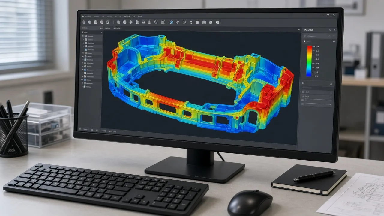
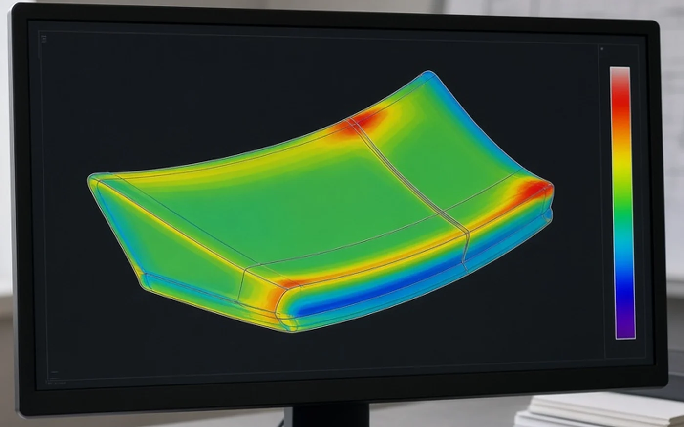
Scanning is not only for creating new designs. It is also one of the fastest ways to inspect a finished part. A molded part is scanned, aligned to its CAD model and shown as a deviation color map: green where the surface is within tolerance, and warmer or cooler colors where it is above or below nominal.
This view makes warpage and twist easy to see on long parts like side skirts and spoilers, where a few CMM points might miss the problem. We supply color maps at ±0.5 mm or ±1.0 mm scales, together with an inspection report. When a critical feature needs higher accuracy, it is measured on our CMMs and reported with the scan.

| Item | Specification |
|---|---|
| Scanner | Shining3D EinScan HX handheld |
| Light sources | Blue laser and infrared |
| Accuracy | 0.04 mm |
| Stitching accuracy | 0.1 mm/m |
| Supporting CMMs | Hexagon Global S 09.15.08; Serein Croma 06.08.06 |
| Deliverable formats | STL, PLY, STEP, IGES, ASC, PDF, PNG |
We sign an NDA before you send parts or data. Reverse-engineered CAD is supplied as a new model based on measurement and is not presented as OEM data. You are responsible for checking that your product does not infringe others’ designs or trademarks; we can help by changing styling features during design.
Engineers on starting a project from a scan instead of a drawing.
“We sent a scan and a photo of the original part, not a drawing. They came back with the questions that mattered — draft angle on two ribs, and which surface we could not touch.”
“We sent over an original bumper trim piece because the measurements in our old drawings were incomplete. Their team used the sample to help sort out the missing details. The process was much more practical than trying to explain everything through photos.”
Names and companies withheld at the customer’s request.
It is the use of a 3D scanner to capture the shape of a physical part, then rebuilding that shape as CAD when no original design data exists.
STL and PLY mesh, STEP and IGES reverse-engineered CAD, ASC point cloud, deviation color maps as PDF or PNG, and inspection reports as PDF.
Our Shining3D EinScan HX has an accuracy of 0.04 mm, with large-part stitching accuracy of 0.1 mm per meter.
No. It is a new model rebuilt from scan data. We label it as reverse-engineered and not original CAD.
Yes. With a handheld scanner we can scan the mounting area on a vehicle, for example a trunk lid for a spoiler or a bumper for a lip.
Yes. We compare scans with CAD and supply deviation color maps at ±0.5 or ±1.0 mm scales.
A 3D scanner captures the whole surface quickly as millions of points. A CMM measures selected points with higher accuracy. We use scanning for shape and full-surface comparison, and CMM for critical dimensions.
Yes. Blue laser handles dark and glossy surfaces better than white light, and very shiny chrome or clear parts can be prepared with a temporary scanning spray.
Both. Most customers use the scan to develop a part that we then tool, mold, finish and inspect in our factory.
Tell us what you need scanned and how the data will be used. We will reply with a plan and a quote.